Monday, March 31, 2008

Setting up the XBees

Now we need to program the XBee radios. There are several ways to do this. You can program a PLC to do it, you can try to program it through a terminal program, or you can use the XCtu program from Maxstream. I recommend using XCtu.

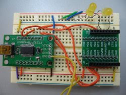
I used the FT232R Breakout board from Sparkfun. You can use FTDI's USB to serial cable, its a little cheaper and just a cable. Solder straight headers to the board. Connect 3.3 to the power strip and the ground to ground. Connect TXD to DIN and RXD to DOUT. Connect RTS to RTS and DTR to DTR. Connect a LED to ON and one to AD5. AD5 can check the mode the radio is in. Connect the board to the USB, note the FT232R needs a mini USB end.


Windows might need some drivers installed. Install them. Open put XCtu and find the COM port that the modem is on. Test to make sure it is there. Download the new firmware.

Click on the modem configuration tag.
Download the then versions of the firmware.
You need to set a network ID- the default is 1111 change it to anything like 2121.
Each modem needs an ID. This is the ATMY configuration. Set one to 1234 and the other to 5678. The modem with MYID 1234, set its destination low to 5678 and visa versa. The destination low tells it which ID it should communicate to. Change the baud rate to whatever baud rate your code is using. Make sure it puts the newest firmware on as well. Click on the write button. In order to access this modems again you need to check on the PC Settings and make sure the baud rate matches.

Arduino to Xbee

Solder the Xbee breakout boards. I recommend soldering the straight headers in first and then the 2mm sockets.


Connect the 9V positive lead to the base of the 9 to 5 volt voltage regulator (I use a 7805). Connect the battery negative lead to ground. The 7805 ground to the ground and then the 5 volts out to the power strip. Connect the Arduino to ground and power. Connect the accelerometer as mentioned in the previous post. Connect the power to the 5 to 3.3 volt voltage regulator (3940IT). Connect its ground and power out. Important note that the 5 volts in and the 3.3 volts out are reversed in the 3940. Use a multimeter to test if you are not sure. Putting 5 volts into the XBee has a good chance of frying it. Using the XBee Sparkfun breakout board connect VDD (power to the 3.3V power) Connect ground to ground. Connect DOUT to the Arduino's RX and the DIN to the Arduino's TX. Connect an LED to the ON pin to test for power. This LED does not need a resistor as it is operating at 3.3 Volts.

Arduino to MAX


Connect your Arduino Mini to the USB Programmer.
TX to TX, RX to RX.
5V to power. Ground to Ground. Reset to Power.
Put an LED in the from the 13 pin to ground. You do not need a resistor it is built in to the 13 pin. This is to indicate power.
Connect the accelerometer power (VDD pin), connect it to ground. Send the X data to Analog 0, the Y data to analog 1, and the Z data to analog 2. Leave the ST pin alone. Note: I usually use an accelerometer that DOES have 90 degree headers. I used the straight header for the picture so you can see the accelerometer better.
Upload the following program and test it...
int ledPin = 13; //Power Pin
int accelerometer[6]; //Array for analog values
int AVGaccelerometer[6]; //Array for Average Values
int avgLimit = 5; //Number values in the Average
int accVal = 0; //Accumulated number for aveerage
int maxLoop = 3;
int inByte = -1;

void setup () {
pinMode(OUTPUT, ledPin);
Serial.begin(19200); //Open Serial
Serial.println("0,0,0,0");
}

void loop(){
for (int i = 0; i < maxLoop; i++){ //first looop get read data
for (int x = 0; x < avgLimit; x++){ //second loop to accumulate data
accelerometer[i] = analogRead(i); //Reads analog values
accVal = accelerometer[i] + accVal;
}
AVGaccelerometer[i] = accVal/avgLimit; //Calculates Average
accVal = 0; //Reset Acculumator
}
delay(10); //Take a rest Serial Port
if (Serial.available() > 0){ //if data is coming in
int inByte = Serial.read();
for (int i = 0; i < maxLoop; i++){ //Send this out!!
Serial.print(AVGaccelerometer[i],DEC); //Data Away!!!
Serial.print(",");
}
Serial.println(); //Send ASCII 10
}
digitalWrite(ledPin,HIGH); //Is this thing on???
}

Starting the Orientation Board

What you need:

Friday, March 28, 2008

Jumping for Joy

ITS ALIVE!!! I am actually speechless and do not know what to write. A warning, this is a rambling narrative. There will be a more technical entry Saturday or Sunday. So I will start from the beginning of the day's work. I connected the Arduino to the Xbee. I then took my multimeter and tested the connections. I have forgotten that my 5 to 3.3 voltage regulator has its pins reversed. Luckily I did not fry my xBee. I went to Xctu and programmed to Xbee radios. As I was about the test them I thought that I have done something inccorrect. I checked the settings again and in fact I had configured the Xbees exactly the same so they would have never communicated to each other. This project I only configured the PAN ID (ATID), the source address (ATMY), and the destination low -which source address to send the message to (ATDL). I had originally set the MY and the DL to the same numbers on both when they should have been the opposite. Quick fix, and I was on my way. I connected everything and it still did not work. I quickly checked my code and remembered I have never changed the baud rate on the Xbee. Going back to XCtu I tried to change the baud rate. One would think this would be simple. Yet there is no baud rate on the read out or anything showing 9600 which is the default. After consulting the owners manual I discovered it is in the serial interfacing section called interface data rate. I gave it the value four which is 19200 baud and set it to both radios. Changing both MAX and the Arduino since they were set to 14400 I decided to give it another try. However I had to relocate first. I hastily packed everything up and moved along. When I unpacked I had broken my voltage regulator. Distraught I came up with the solution to use the FTDI board I use to configure the Xbees because it has a 3.3 volt output. I plug it in run MAX and it works. Until I notice it is reading it through the Arduino Mini USB programmer. Disconnect that and...it stops working. I play with the settings on MAX serial and it gets worse. Restart MAX and...it works. Restart it again and it works again! So we have a wireless orientation controller. There are still some issues with the data I need to hammer out as the orientation can be flawed.
Below are pictures of a screen capture and of the horrid breadboard monster I created.


Wednesday, March 12, 2008

Orientation Running in MAX/MSP

After a rather long two day battle with MAX/MSP, I got the orientation to work in MAX/MSP. It works fairly well; occasionally it has some issues with its 180 degree counter part but that can be worked out by zero counting or not allowing movement beyond a certain threshold. I will have pictures up tomorrow of the MAX/MSP program in use and hopefully a video in a weeks time. I now need to convert it to Processing and from there something else, C++ or Python (if I can find easy to use serial libraries). Either one I will have to relearn how to program the language. So for now I will stick to MAX and Processing. Next week is spring break so I will most likely be traveling, doing reading, and sightseeing. So more theory and concept to follow rather then technical material. I know many people have problems with the MAX serial object. Reading some examples from Tom Igoe's Making Things Talk I figured out a way to prevent some errors. MAX tends to easily get flooded with serial data and either locks up or ceases to function correctly. By having an IC on the other serial end (in my case an Arduino Mini) wait for a response from the computer before sending data MAX is fine with the data flow. I have yet to see it crash or lock up. I currently have the baud rate at 9600 but will start to speed up the connection to see how fast MAX can handle the data.

Monday, March 10, 2008

Orientation to begin again

Okay, I have the math and an example in MAX/MSP that uses the iPhone to detect the iPhone's orientation. The example and the math was from Liubo Borissov and many thanks to him. I don't have an iPhone but I will connect MAX to my Arduino. In good news for my wallet, I only need one accelerometer. The examples I was reading were only for accelerometers with two axises. The accelerometers I have are three axis accelerometers. That is very good so I can free up room in the element's vessel and inputs into the Arduino. The math works something like this. I form a vector from the origin to the change in gravity (static - dynamic). This is done from subtracting the dynamic x,y,z from the static x,y,z. From there I can create orientation from this vector by calculating the angles. So the vector value would be x0, y0, z0. I take the arc cosine of y0 divided by the length of the vector. Also the arc tangent of x0 divided by z0. From this I should get pitch and roll. I will put up the code and explain it more there. The static x,y,z are the threshold of the accelerometer standing still. Dynamic x,y,z would be anything outside that threshold.

Wednesday, March 05, 2008

Lack of Wireless Experiments

I got sick over the weekend and was not able to play with my Xbees. Hopefully tomorrow I will get a small program to send data to Processing and MAX. I will also play with location detection but that will take more than one week. I am interested in how MAX reacts as its serial object is not the most reliable thing on Earth. I am praying that in MAX 5 this issue has been solved. I look forward to MAX 5 as well. I downloaded the development tools for the XBee. I will do some reading but I do not think I will go to that extreme.